

INTRODUCTION
Implant placement in an edentulous posterior maxillary site faces challenges related to the resorption of the crestal ridge and enlargement of the maxillary sinus. Both of these events are normal occurrences following the loss of the premolar or molar in the posterior maxilla. The result is insufficient crestal height to accommodate implant placement.
In 1994, Summers1,2 was the first to publish on the use of osteotomes utilizing a crestal approach to elevate the maxillary sinus membrane and place osseous graft material to increase the crestal height to allow implant placement in the deficient posterior maxilla. Prior to this innovation, a lateral approach was utilized to elevate the sinus in preparation for implant placement. Dr. Hilt Tatum had developed the lateral window sinus approach in the 1970s, but the technique was not published until 1980.3,4
The lateral approach is more complicated surgically, has more postoperative issues during initial healing, and has more potential problems than the crestal approach. Lateral sinus elevation is still indicated when the crestal bone is less than 3 mm, and multiple implants will be placed in the quadrant, requiring a larger area to be elevated, whereas the crestal approach is well-suited when the current crestal height is 3 mm or greater and either a single or 2 adjacent implants are planned. When the current crestal height is 4 mm or greater, sufficient elevation and grafting may be performed in conjunction with simultaneous implant placement, as stability of the implant is possible, and allowed to heal before the restorative phase is initiated. Should the existing crestal height be between 3 and 5 mm, crestal augmentation may be performed, and delayed implant placement can be performed. Following initial healing of the sinus augmentation, at the subsequent surgery, additional crestal elevation can be performed, and implants can be placed.
Contraindications to the crestal approach include, as mentioned, a crestal height of less than 3 mm and a ridge width of 3 mm or less than the planned implant width. When those factors are present, a lateral approach should be utilized.
A CRESTAL SINUS ELEVATION PROCEDURE
Depth stop drills improve accuracy and, in combination with non-cutting drill tips, aid in preventing the tearing of the sinus membrane during the elevation process.
The drills are designed so that autogenous bone particles are pushed up through the opening in the sinus floor beneath the membrane as each progressive (larger diameter) drill is used. The drill removes bone from the inner wall of the osteotomy with a counterclockwise rotation. (Drill sets are available for both clockwise or counter-clockwise rotation.) This pushes the bone apically to elevate the membrane. The use of a sinus elevation probe after each drill in the 1.5- to 2.2-mm gold series depth is done to feel/check for a perforation through the bone at the sinus floor. The drills should not penetrate the floor of the sinus by more than 1 mm, leaving the membrane intact.
The Guide Right Sinus Elevation kit (DePlaque) contains all the components, drills, and tools to perform the crestal sinus elevation procedure (Figure 1). The Guide Right drills are available in 5 series of diameters with a 2° taper in lengths of 4, 5, 6, 7, 8, 9, and 10 mm (Figure 2). Each drill is run at 600 to 800 rpm in the surgical handpiece. The drills may be used with a guided approach or freehand, depending on the surgeon’s preference.
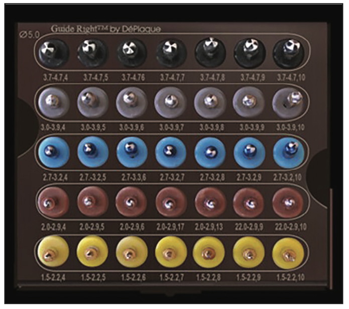
Figure 1. The Guide Right Sinus Elevation kit and its components (DePlaque), available for both clockwise and counter-clockwise rotation.
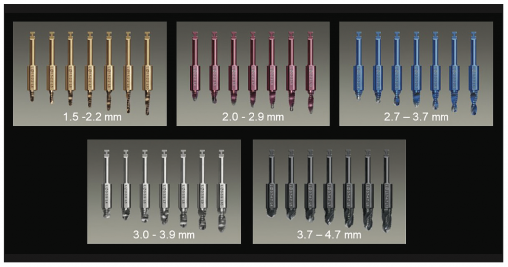
Figure 2. Drill series for crestal sinus elevation with 2° tapered depth stops utilized.
CRESTAL SINUS ELEVATION PROTOCOL
When using a guided approach or a flapless protocol, the crestal sinus elevation drill sequence is followed (Figure 3, steps 1, 2, and 3). Subsequent gold drills that are 4 and 6 mm long are used to depth until the bone is penetrated and the membrane is felt. After the use of each 4- to 6-mm-length gold drill, the site is evaluated with a sinus elevation probe to tacitly feel if the membrane has been contacted. The probe should be used gently to avoid perforation of the sinus membrane. If the membrane can be felt, longer drills are not utilized, and further site preparation is done with the wider Guide Right Sinus drills of the same length. For illustration purposes, we will assume that the depth before membrane contact is 6 mm.
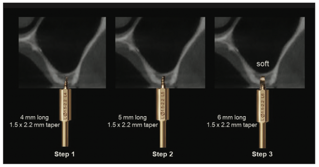
Figure 3. Steps 1 to 3: initial steps to determine the level of the sinus membrane and thickness of the crestal bone.
To verify an intact sinus membrane, it can be checked using the Valsalva Maneuver. This maneuver involves pinching the patient’s nose and having the person try to blow his or her nose while you watch to see if any bubbles escape from the osteotomy site. If no bubbles or blood escape, the membrane has most likely not been perforated. This should be checked prior to any graft material being placed into the osteotomy. After testing with the Valsalva Maneuver, if the membrane has been perforated, select a drill 1 mm shorter than the working length that is wider than the prior drill. Use those larger diameter drills, 1 mm shorter in length, until you reach the final diameter needed.
A Rose series drill (2 to 2.9 mm) in 6 mm length is used until the drill stop contacts the crest, which pushes the autogenous bone particulate to further elevate the sinus membrane.
Cut an OsteoGen Plug (OPS625-10 Slim [IMPLADENT LTD]) into small pieces that are 3 to 4 mm long. Using the Concave Plugger (small end), compress all pieces, one piece at a time, into the osteotomy. Check again for sinus membrane perforation with the Valsalva Maneuver. Continue to increase the sinus elevation with more of the collagen or bone product until you have reached the desired implant length. Check the site with a periapical radiograph prior to placing the implant to verify the graft is confined in the area and not dispersed throughout the sinus.
Subsequent drills increasing in diameter, from Blue series (2.7 to 3.2 mm) to the Silver series (3 to 3.9 mm) in 6 mm length, are utilized to push additional autogenous particulate, widening the diameter of the osteotomy to elevate the sinus membrane (Figure 4, step 4).
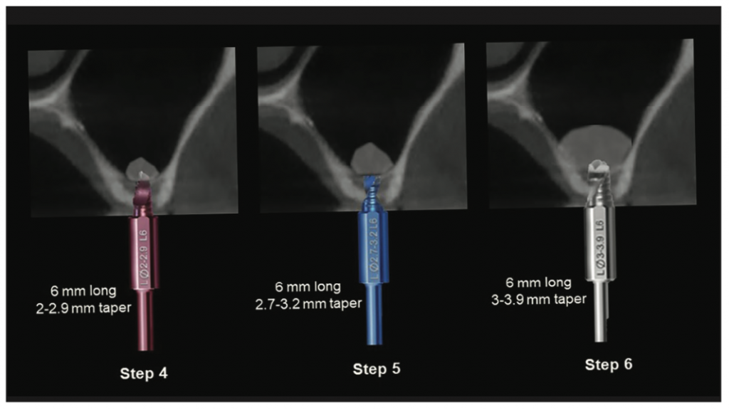
Figure 4. Steps 4 to 6 utilized to push additional autogenous bone particulate into the sinus.
The final diameter of the Guide Right Sinus Elevation drills should be narrower than the planned implant’s diameter so that the implant, upon placement, engages the osseous walls crestally, providing initial implant stability (Figure 4, steps 5 and 6).
When the planned implant is a greater diameter than 4.7 mm, the Black series drills are used, which have a diameter of 3.7 mm at the tip and 4.7 mm at the drill stop. This drill is then used after filling the osteotomy with additional graft material, in this illustrated case to the 6-mm drill stop (Figure 5, step 7). The Concave Plugger is then used to add additional graft material and gently apply apical pressure to further lift the sinus membrane, allowing the graft material to elevate the membrane circumferentially and apically (Figure 5, step 8). The implant is then placed, achieving lateral compression with the crestal walls and achieving initial stability (Figure 5, step 9). A cover screw or healing abutment is placed, and soft tissue is sutured around to get primary closure if a flap is reflected. Due to the less dense bone of the posterior maxilla, it is not recommended to immediately load these implants but to allow the graft material to mineralize and the implant to osseointegrate for 4 to 6 months before the restorative phase is initiated.
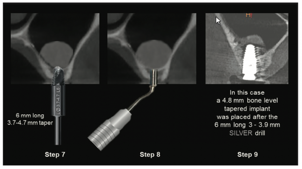
Figure 5. Steps 7 to 9 utilized to push additional graft material with apical pressure to further elevate the sinus membrane.
DRILL TEMPERATURE AND ITS EFFECTS
A study on the effects of drill sharpness completed by Ercoli et al5 examined temperature increases with different drilling protocols. One of the parameters examined was the temperature of the drilling protocol. The results indicated drills were not significantly different at depths of 5 mm or 15 mm, or between 2- or 3-mm-diameter drills. The temperatures generated by the different types of drills were not significantly different. Clinically harmful temperatures were detected only at a depth of 15 mm during osteotomy preparations and coincided with a marked decrease in the rate of drill advancement with a resulting continuous drilling action. They concluded the properties significantly affect cutting efficiency and durability. Coolant availability and temperature were the predominant factors in determining bone temperatures. Continuous drilling in deep osteotomies can produce local temperatures that might be harmful to the bone.5 It has been shown in an in vitro study in bovine ribs that the use of a refrigerant solution at a temperature of 6°C reduces the increase of bone temperature during the preparation of implant sites compared with the physiological solution at the temperature of 23.7°C.6
There are benefits of cold drilling when creating osteotomies, especially when a flapless approach is being used with a surgical guide. Irrigation is unable to reach apical to the soft tissue during a flapless approach, and a surgical guide may hamper the irrigant from cooling the drills. Because flapless protocols involve serial drilling by increasing drill lengths at 1-mm intervals, the drills are pre-cooled, and irrigation is not necessary nor required. The drills can be pre-cooled by placing them in a refrigerator’s freezer for one hour prior to surgery. The sinus elevation protocol calls for serial drilling, increasing the depth by 1 mm at a time, which is hardly long enough for the drill to heat up to significantly injure the bone cells. Once the depth of the osteotomy is reached, the width of the osteotomy is increased by less than 1 mm with each increasing drill diameter, also using cooled drills. In serial drilling of 1-mm increments of bone depth (4-, 5-, 6-, 7-, 8-, 9-, and 10-mm lengths), switching to a fresh cooled drill for each step until the final depth is reached results in less trauma to the alveolar bone and less discomfort to the patient. After the appropriate depth is reached, the osteotomy width is also increased in small steps, limiting the trauma and heat produced by using pre-cooled drills to remove a very small amount of bone pushed apically.
CASE REPORTS
Case 1
A 70-year-old male patient presented with missing molars in the maxillary right posterior, desiring replacement to improve mastication. The first and second molars had been extracted several years before. A periapical radiograph was taken, and pneumatization of the sinus was noted. The crestal height was estimated at 6 mm (Figure 6). Treatment was discussed, and it was recommended to place an implant at the first molar site without implant placement at the second molar site. The patient was advised sinus elevation would be required for implant placement, and treatment recommendations were accepted.
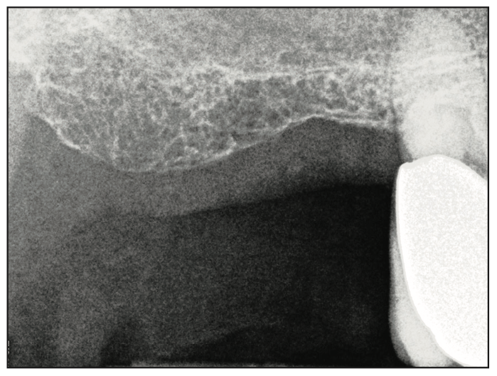
Figure 6. Periapical radiograph demonstrating an estimated crestal height at site 3 of 6 mm.
An impression was taken, and a study model was made to fabricate a diagnostic guide utilizing Guide Right sleeves to be utilized during the CBCT. A cone-beam radiograph was taken with the diagnostic guide in place. The scan was imported into CS 3D Imaging planning software (Carestream Dental). A virtual implant was placed in the preferred position (Figure 7). It was determined an angle correction of 12° would be required based on the anatomy present to be incorporated into the surgical guide design (Figure 8). A corrected surgical guide was fabricated to place the planned implant in an ideal position related to the anatomy, and it was prosthetically driven.
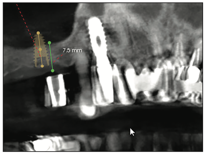
Figure 7. CBCT views during the planning stage with Guide Right sleeves in the diagnostic stent with measurement of the crestal bone height and overlaying soft tissue available at site 3.
The patient returned, and consent forms were reviewed and signed by the patient. Following local anesthetic placement, a flapless surgical approach was utilized with the Guide Right surgical guide to follow the Guide Right sinus elevation protocol previously described. Upon creation of the osteotomy and identification of the sinus membrane, Puros (RTI Surgical) OsteoGen and 50 μg. Infuse bone graft (BMP-2) are placed into the osteotomy.
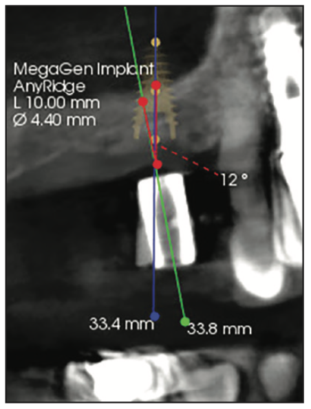
Figure 8. During virtual planning, it was determined an angle correction of 12° would be required based on the anatomy present (green line: long axis of Guide Right sleeve, blue line: long axis of the virtual implant, red line: angle correction required) to be incorporated into the surgical guide design.
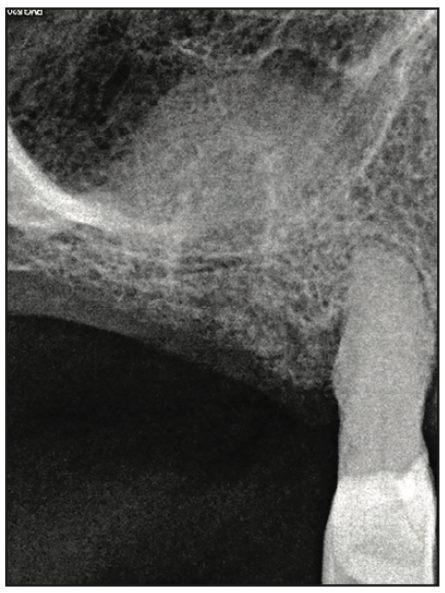
Figure 9. Periapical radiograph following placement of the collagen plug strips of allograft prior to implant placement.
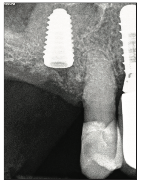
Figure 10. Periapical radiograph following immediate placement into the elevated sinus at site 3.
OsteoGen Plug 1020 (IMPLADENT LTD) was used to elevate the sinus membrane. The plug was sectioned into quarters lengthwise. Then 50 to 100 μg of BMP-2 in 0.40 ml sterile H2O was applied to the plug pieces for 15 minutes prior to application. Minimal H2O is recommended to avoid dilution of the BMP-2 once inserted into the sinus area.7-9 Each piece of the plug is then cut into smaller pieces for the elevation of the sinus membrane. Pieces of the 50 to 100 μg of BMP-2 laced plug are introduced into the osteotomy with collage pliers and pressed apically with the plugger. The last Guide Right sinus drill was then utilized to gently move the graft apically while running counterclockwise to elevate the membrane. A periapical radiograph was then taken to verify sinus elevation and containment of the graft at the site (Figure 9). The osteotomy was widened utilizing the osteotomy final drill for the implant to be placed (Mega’Gen), and a 5- × 10-mm implant was placed (Mega’Gen). The implant length selected should not be greater than the height of the elevation. A periapical radiograph was taken to document implant placement and was within the limits of the sinus elevation (Figure 10). A 2.5-mm healing abutment was placed, the patient was dismissed, and healing would be allowed for osseointegration prior to initiation of the restorative phase.
Case 2
A 76-year-old male patient presented for implant placement at site 14 that had a missing tooth. A periapical radiograph noted 3 to 4 mm of residual crestal bone at the site. A diagnostic CBCT scan guide was created, and a CBCT scan was taken. The scan data was imported into virtual planning software, and a virtual implant was placed at the site (Figure 11).
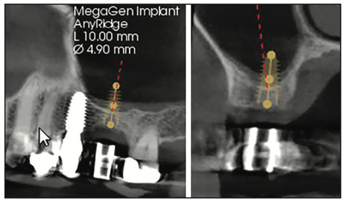
Figure 11. CBCT views during the planning stage with Guide Right sleeves in the diagnostic stent illustrating the 3- to 4-mm crestal bone height available.
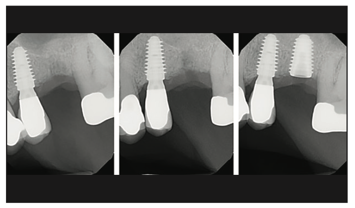
Figure 12. Periapical radiographs taken at various stages of the crestal elevation (left: following initial reverse drill osteotomy, middle: following sinus elevation, right: following implant placement).
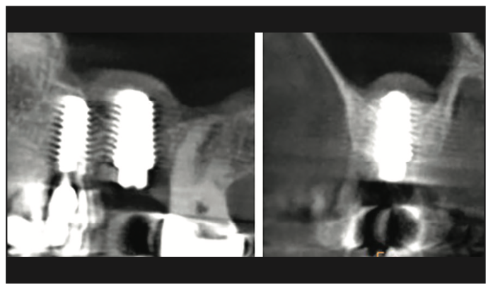
Figure 13. CBCT views following crestal sinus elevation and implant placement illustrating the gain in crestal height to accommodate the implant at site 14.
The patient returned, and consent forms were reviewed and signed. A similar protocol as described for the prior case was followed. Following an initial reverse drill osteotomy with the Guide Right sinus elevation drills, a periapical radiograph was taken (Figure 12, left). Collagen plug pieces with BMP-2 were utilized to elevate the sinus, and a periapical radiograph was taken (Figure 12, middle). A 5- × 10-mm Mega’Gen tapered implant was placed, and a periapical radiograph was taken to document the implant and graft (Figure 12, right). A 2.5-mm healing abutment was placed, and a CBCT scan was taken documenting that the implant was encased in graft material, especially apically (Figure 13). The patient was dismissed, and healing would be allowed for osseointegration prior to initiation of the restorative phase.
Case 3
A 74-year-old female patient presented with a missing tooth 15 and tooth 16 present in a good position, requesting an implant to replace tooth 15 instead of a fixed bridge from 14 to 16. A periapical radiograph noted 3 to 4 mm of residual crestal bone at the site. Implant planning was done for maxillary left second molar that required sinus elevation. A diagnostic CBCT scan guide was created, and a CBCT scan was taken. The scan data was imported into virtual planning software, and a virtual implant was placed at the site (Figure 14).
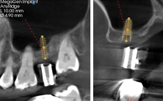
Figure 14. CBCT views during planning stage with Guide Right sleeves in the diagnostic stent illustrating the 3- to 4-mm crestal bone height available at site 15.
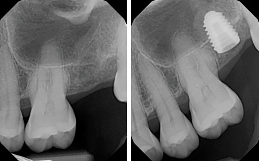
Figure 15. Periapical radiograph taken following crestal sinus elevation (left) and after implant placement (right).
The patient returned, and consent forms were reviewed and signed. A similar protocol as described for the prior cases was followed. Following sinus elevation with the Guide Right sinus elevation drills, collagen plug pieces with BMP-2 were utilized to elevate the sinus, and a periapical radiograph was taken (Figure 15, left). A 5- × 10-mm Megagen tapered implant was placed, and a periapical radiograph was taken to document the implant and graft (Figure 15, right). A 2.5-mm healing abutment was placed, the patient was dismissed, and healing would be allowed for osseointegration prior to initiation of the restorative phase.
Case 4
A 69-year-old female patient presented 3 months after tooth No. 14 had been extracted for evaluation for implant placement at the site. Minimal bone was noted below the sinus after a CBCT scan was taken with a Guide Right diagnostic stent (Figure 16). Minimal crestal height was confirmed. A surgical guide was fabricated with Guide Right sleeves.
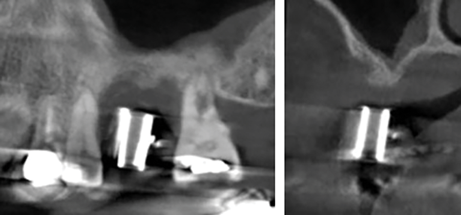
Figure 16. CBCT views during the planning stage with Guide Right sleeves in the diagnostic stent illustrating the minimal crestal bone height available.
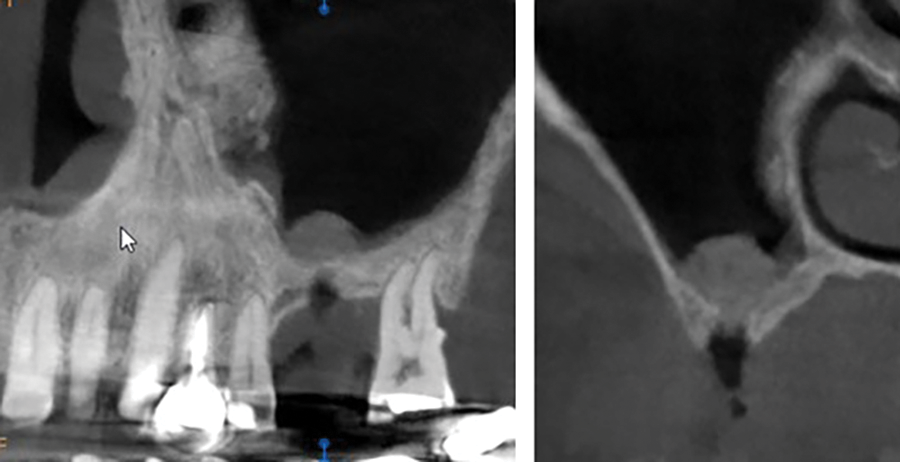
Figure 17. CBCT after the initial reverse osteotomy pushed the crestal bone material to raise the sinus membrane.
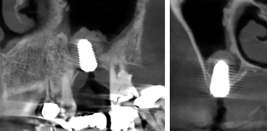
Figure 18. CBCT following additional graft placement to further elevate the sinus membrane and implant placement.
The patient returned, and consent forms were reviewed and signed. A similar protocol as described for the prior cases was followed. Following initial elevation, a CBCT scan was taken to confirm the initial graft was contained and had not spread inside the sinus due to perforation of the membrane (Figure 17). Further graft placement and elevation were performed, and a 5- × 10-mm Mega’Gen implant was placed. A CBCT scan was taken to document the implant placement and amount of sinus elevation, confirming it was contained around the implant (Figure 18). A cover screw was placed and the patient was dismissed, and healing would be allowed for osseointegration prior to initiation of the restorative phase.
CONCLUSION
Loss of crestal height is a frequent occurrence in the posterior maxilla, complicated by periodontal bone loss that may be a causative factor for the loss of that tooth and pneumatization of the sinus. A crestal approach to increase crestal height to accommodate implant placement is a simpler, less traumatic approach than lateral sinus augmentation. The technique described using a diagnostic CBCT stent, virtual planning, and surgical guide allows a flapless approach to the procedure. Utilization of the Guide Right sinus elevation instrumentation decreases the potential for membrane perforation during elevation and osteotomy creation. This results in a simpler, more predictable approach to implant placement in the resorbed posterior maxilla.
REFERENCES
1. Summers RB. A new concept in maxillary implant surgery: the osteotome technique. Compendium. 1994.15(2):152, 154–6.
2. Summers RB. The osteotome technique: Part 3—Less invasive methods of elevating the sinus floor. Compendium. 1994;15(6):698, 700, 702–4 passim.
3. Boyne PJ, James RA. Grafting of the maxillary sinus floor with autogenous marrow and bone. J Oral Surg. 1980;38(8):613–6. https://pubmed.ncbi.nlm.nih.gov/6993637/
4. Tatum H Jr. Maxillary and sinus implant reconstructions. Dent Clin North Am. 1986;30(2):207–29.
5. Ercoli C, Funkenbusch PD, Lee HJ, et al. The influence of drill wear on cutting efficiency and heat production during osteotomy preparation for dental implants: a study of drill durability. Int J Oral Maxillofac Implants. 2004;19(3):335–49.
6. Di Fiore A, Sivolella S, Stocco E, et al. Experimental analysis of temperature differences during implant site preparation: Continuous drilling technique versus intermittent drilling technique. J Oral Implantol. 2018;44(1):46-50. doi:10.1563/aaid-joi-D-17-00077
7. Nevins M, Kirker-Head C, Nevins M, et al. Bone formation in the goat maxillary sinus induced by absorbable collagen sponge implants impregnated with recombinant human bone morphogenetic protein-2. Int J Periodontics Restorative Dent. 1996;16(1):8-19.
8. Boyne PJ, Marx RE, Nevins M, et al. A feasibility study evaluating rhBMP-2/absorbable collagen sponge for maxillary sinus floor augmentation. Int J Periodontics Restorative Dent. 1997;17(1):11-25.
9. Freitas RM, Spin-Neto R, Marcantonio Junior E, et al. Alveolar ridge and maxillary sinus augmentation using rhBMP-2: a systematic review. Clin Implant Dent Relat Res. 2015;17 Suppl 1:e192-201. doi:10.1111/cid.12156
ABOUT THE AUTHORS
Dr. Meitner graduated from Marquette University in Milwaukee after completing a tour of duty in the US Navy, completed his certificate and board examinations in periodontics at the Eastman Institute for Oral Health at the University of Rochester in New York, and remains a part-time professor of clinical dentistry in the Department of Periodontology at the university. He has been in private practice in periodontics for more than 30 years in Pittsford, NY, and is the developer of the Guide Right protocol. He can be reached at swmeit4@gmail.com.
Dr. Kurtzman is in private general practice in Silver Spring, Md. A former assistant clinical professor at the University of Maryland, he has earned Fellowships in the AGD, the American Academy of Implant Prosthodontics, the American College of Dentists, the International Congress of Oral Implantologists (ICOI), the Pierre Fauchard Academy, and the Association of Dental Implantology; Masterships in the AGD and ICOI; and Diplomate status in the ICOI and the American Dental Implant Association. He has lectured internationally, and his articles have been published worldwide. He has been listed as one of Dentistry Today’s Leaders in Continuing Education since 2006. He can be reached via email at dr_kurtzman@maryland-implants.com.
Disclosure: Dr. Meitner is a product developer and non-paid consultant for DePlaque. Dr. Kurtzman reports no disclosures.