

INTRODUCTION
The past 3 years of experience in our practice have made it clear that 3D printing provides numerous benefits for patients and practices alike. The digital impression-taking process is far more comfortable for the patient than the conventional process of using an alginate and pouring it up in stone. The 3D printing process eliminates the bubbles and imperfections often resulting from the conventional fabrication approach while delivering far better precision and durability. The ability to 3D print in the office also reduces the number of visits to the practice—which is particularly important to patients who live far from the practice. If a printed appliance is ever lost or damaged, a replacement can quickly be printed using the existing model. In addition, utilizing a digital workflow makes it easier for patients to visualize how their teeth will look at the temporary stage, reducing the number of adjustments and lab remakes at the final stage. Finally, patients benefit from the same-day 3D printing of retainers, which avoids the risk of relapse that could occur if the patient fails to appear for the follow-up appointment to pick up a lab-made retainer.
Our practice also enjoys several benefits from 3D printing, including streamlining workflow, significantly reducing lab work and rework expenses, reducing shipping expenses, and providing a more predictable result with greater control.
The benefits of 3D printing are especially significant when patients require orthodontic treatment followed by restorative treatment, as illustrated in the following 2 cases.
CASE REPORTS
Case 1
A 46-year-old male patient presented with a medical history including cleft lip and palate repair and also had a missing upper left lateral incisor (Figure 1). His upper midline had shifted to the left of his facial midline due to the asymmetry (Figure 2). Only 3 mm of space was available between the upper left canine and central incisor for a replacement for tooth No. 10. There was an anterior crossbite of No. 9 and No. 11 with Nos. 22 to 24 (Figure 3), causing fremitus and a horizontal fracture line on No. 9. In addition, No. 8 was in edge-to-edge occlusion with Nos. 25 and 26, leading to excessive incisal wear on No. 8 as well as No. 7 (Figure 4). The patient desired not only to improve the aesthetics of his smile but also to address the trauma caused by the malocclusion.
Figure 1. Initial upper arch image showing missing tooth No. 10.
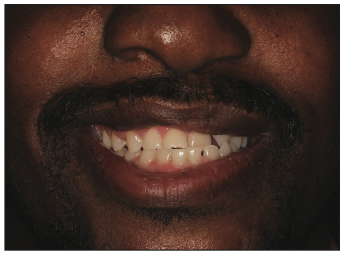
Figure 2. Initial low smile view showing the upper midline to the left of the facial midline.
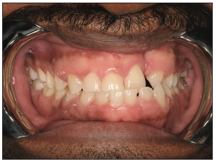
Figure 3. Initial intraoral image showing missing No. 10 and the crossbite of Nos. 9 and 11 with Nos. 22 to 24.
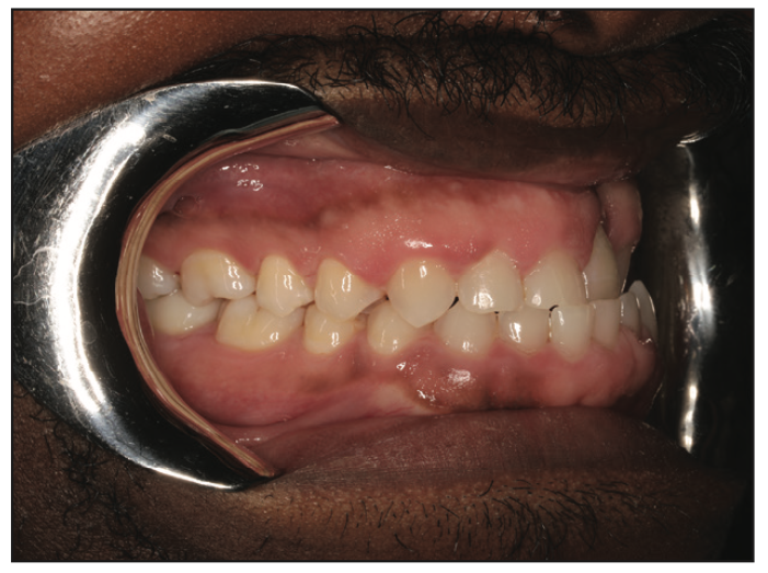
Figure 4. Initial intraoral edge-to-edge view between No. 8 and Nos. 25 and 26.
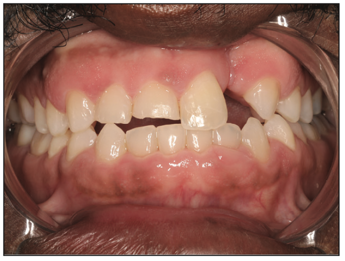
Figure 5. Post-ortho intraoral view showing space created for Nos. 7, 8, and 10 and the corrected crossbite.
In order to restore the patient’s dentition, orthodontics was necessary, and the patient preferred clear aligner therapy. Invisalign aligners were used to create 7 mm of space to replace No. 10 (Figure 5), to intrude Nos. 7 and 8 for adequate clearance for the future crowns, to close the spacing on the lower, and to correct the crossbite. An implant was not an option due to an inadequate amount of available bone. Instead, we decided to place crowns on Nos. 7 and 8 and a bridge for Nos. 9 through 11. The orthodontic treatment took 17 months and included 2 refinements. During the Invisalign treatment (Align Technology), A1 shade pontic paint was placed in the No. 10 pontic on the aligner, so it was not obvious the patient was missing a tooth. This is a major advantage of using clear aligners when a patient is missing an anterior tooth and why Invisalign is preferred in these situations (Figure 6).
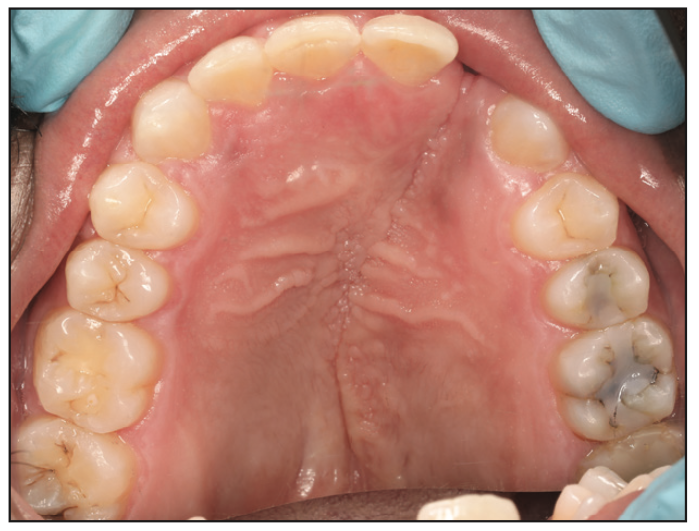
Figure 6. Post-ortho maxillary arch.
Once orthodontic treatment was complete, the attachments were removed, and using a digital scanner (iTero Element 5D [Align Technology]), STL files of the final occlusion were created and temporary retainers were printed in the office on the 3D printer (3Demax [DMG]) using a 3D printing resin (LuxaPrint Model [DMG]). The STL files were uploaded to the design software (3D A.I. Mockup Design [SmileFy]), which was used to design teeth Nos. 7 through 11 (Figures 7 and 8). The STL files were then imported to the nesting and slicing software (Netfabb [Autodesk]) and a model of the patient’s upper arch with the 3D designed anterior teeth was printed using LuxaPrint Model. A positive pressure machine was used to fabricate the stent for temporary crowns on Nos. 7 and 8 as well as a temporary bridge for Nos. 9 through 11 (Figures 9 and 10). The model was run through the curing unit (3Decure [DMG]) and washing unit (3Dewash [DMG]).
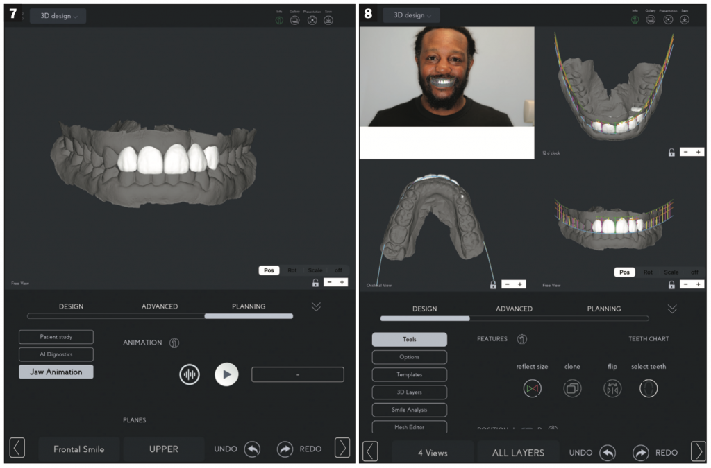
Figures 7 and 8. Crown and bridge designed using SmileFy software.
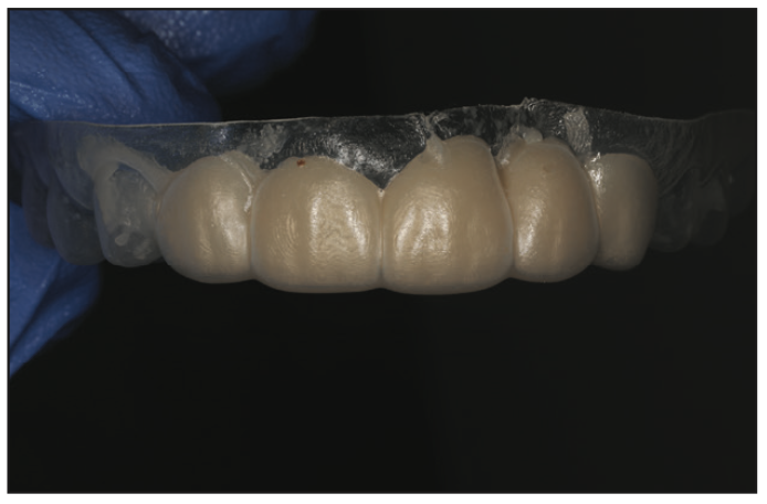
Figure 9. Stent.
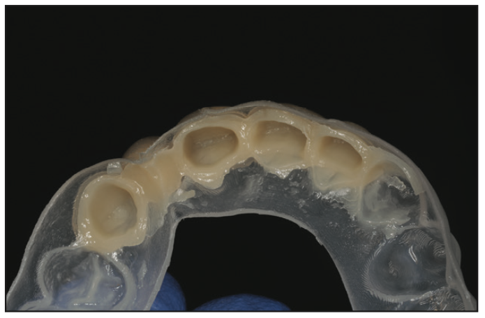
Figure 10. Stent.
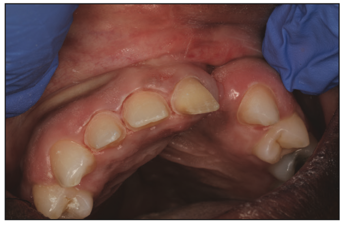
Figure 11. Teeth prepped for restorative treatment.
For the temporary crowns and bridge, a high-performance crown and bridge material (LuxaCrown [DMG]) was used. After prepping the teeth (Figure 11), temporaries were placed (Figure 12) using an aesthetically oriented temporary cement (TempoCem ID [DMG]). I use this for all of my temporaries due to its uncanny ability to allow the temporary to stay on yet leave no residue on the tooth when it is removed. From the design model, which had been printed earlier, a retainer was printed to protect the temporaries and prevent the teeth from shifting prior to the final restoration.
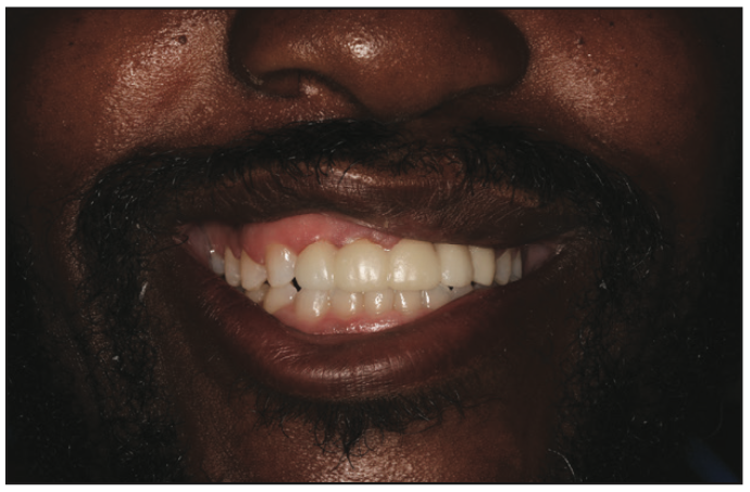
Figure 12. Patient with temporaries fabricated with LuxaCrown (DMG) and cemented with TempoCem ID (DMG).
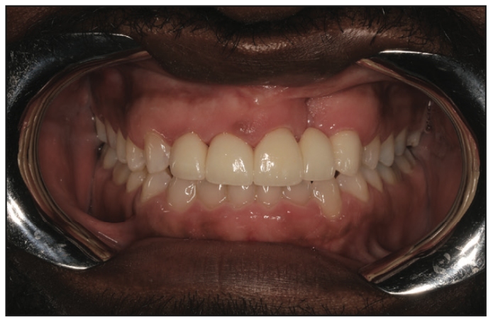
Figure 13. Final intraoral image.
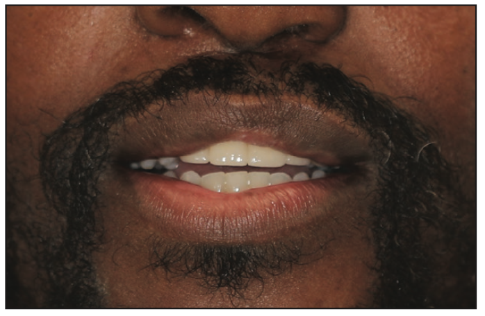
Figure 14. Patient with final restoration.
The final design of the temporary was sent to the outside lab to give the lab a clear idea of what the permanent restoration should look like. The permanent restorations were fabricated using multilayered KATANA Zirconia [Kuraray Noritake]). Once the final restoration was cemented (Figure 13), we took a scan immediately afterward and printed a model for a permanent retainer the same day. The patient was extremely happy with the outcome (Figure 14).
Case 2
A 50-year-old female presented who was unhappy with the aesthetics of her veneers that had been placed more than 20 years ago (Figure 15). She exhibited significant recession around the veneers and significant staining on the margins of the veneers and on the composite that had been placed over the roots of the teeth (Figure 16). In order to achieve the broad smile she desired, orthodontic treatment was necessary. This was to correct her unilateral functional posterior crossbite caused by her narrow palate and a shift of the mandible to the right when she closed her mouth. We also needed to correct the upper midline, which had a significant cant to her left (Figure 17).
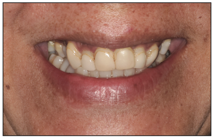
Figure 15. Patient with 20-plus-year-old veneers.
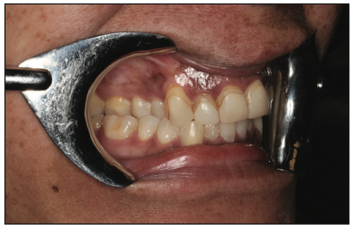
Figure 16. Staining visible on margins and composite buildups and the posterior crossbite.
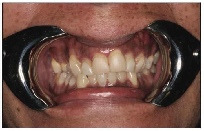
Figure 17. The upper midline’s slant to patient’s left is apparent.
For this case, the patient preferred fixed appliances rather than removable ones. Brackets (Damon System [Ormco]) were designed using orthodontic design software (Insignia Advantage [Ormco]). Her maxillary arch width was increased by uprighting the lingually inclined posterior teeth, and the crossbite was corrected with crossbite elastic on her right side. The orthodontic treatment took 14 months (Figures 18 to 22).
Figure 18. Pre-ortho view of the mandible.
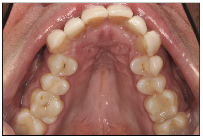
Figure 19. Pre-ortho view of the maxilla.
Figure 20. Post-ortho view of the mandible.
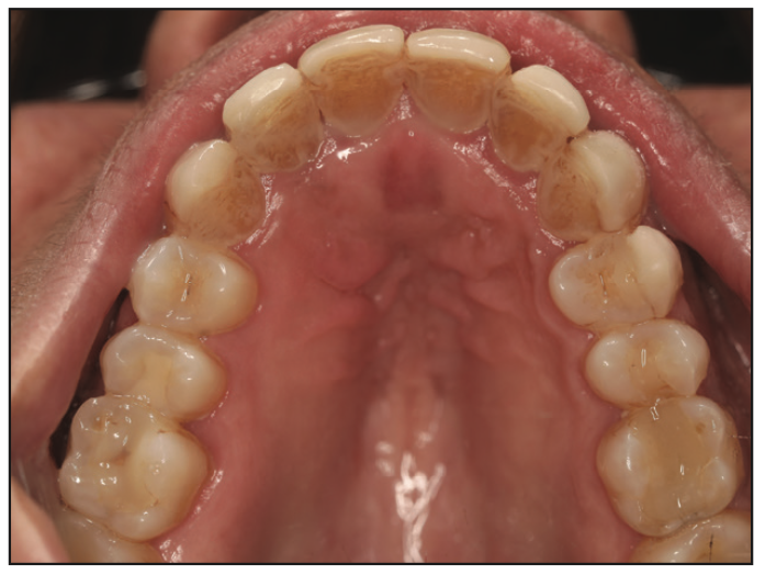
Figure 21. Post-ortho view of the maxilla.
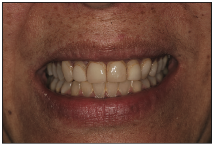
Figure 22. Post-ortho view of the patient’s smile.
When her orthodontic treatment was complete, her teeth were scanned using the iTero Element 5D, the brackets were digitally removed from the STL file using triangle mesh software (Meshmixer [Autodesk]), and the 3Demax printer was used to create upper and lower retainers. Creating retainers ahead of time was advantageous since, at the bracket removal appointment, her retainers were able to be delivered immediately.
To plan her restorations, the same STL file was imported into the SmifeFy design software, which was used to design 8 temporary veneers from the first premolar to the first premolar. The model was printed (Figure 23) using LuxaPrint Model 3D printing resin, and a positive pressure machine was used to create a stent and retainer (Figure 24). After removing the old veneers and prepping the teeth for new restorations, the stent was used to fabricate the temporary veneers (Figure 25) with a temporary crown and bridge material (Luxatemp [DMG]). These were cemented using an invisible temporary cement (TempoCem ID [DMG]).
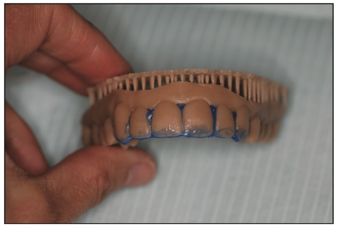
Figure 23. The 3D printed model with blockout for fabricating retainers.
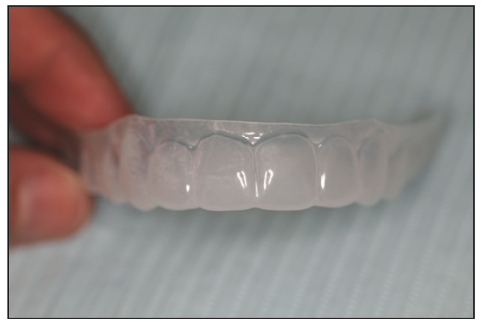
Figure 24. The 3D printed stent from the designed STL file.
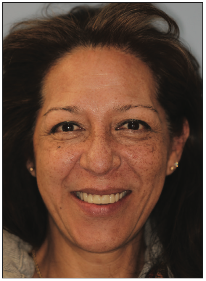
Figure 25. The patient with temporary veneers cemented.
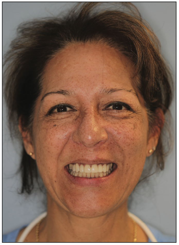
Figure 26. The patient with permanent veneers cemented.
While I was very pleased with the look and fit of the temporaries, the patient was accustomed to her teeth being shorter and asked that her upper anterior teeth be shortened slightly. Her request was easy to accommodate, as the design file was simply sent to the outside lab, and they were instructed to shorten the upper anterior teeth by 1 mm. The final veneers were fabricated using a lithium disilicate glass-ceramic (IPS e.max [Ivoclar]). They were cemented using PANAVIA Veneer LC (Kuraray Noritake). The patient was very happy with the final result (Figure 26).
CONCLUSION
Our 16-operatory practice does a great deal of orthodontic work, often followed by restorative work, as in the 2 cases above, and the use of 3D printing in this work has been a real game-changer for our patients and us.
ABOUT THE AUTHOR
Dr. Latham received a BS degree from Boston University, where she was her class valedictorian, and a DDS degree from the University of Michigan School of Dentistry. She is currently a general dentist in a 4-doctor, 16-operatory practice in Stratford, Conn. She previously served in a military dental clinic in Rota, Spain, and in a private practice in Virginia Beach, Va. She has completed numerous postdoctoral courses in orthodontics and Invisalign. Dr. Latham is a recipient of the William S. Kramer Award of Excellence from Omicron Kappa Upsilon, a member of the International Association of Orthodontics, and an Invisalign Platinum Provider. She grew up in New Zealand and moved across the Pacific in 2001 to attend Boston University and compete as a track and field athlete. She can be reached at julialathamdds@gmail.com.
Disclosure: Dr. Latham reports no disclosures.