The study was conducted in accordance with the World Medical Association Declaration of Helsinki on medical research ethics. All experimental protocols in this clinical retrospective study were approved by the Ethics Committee of Shanghai Ninth People’s Hospital.
Patients
This study was performed in the Department of Oral and Craniomaxillofacial Surgery, Ninth People’s Hospital, Shanghai Jiao Tong University School of Medicine, Shanghai, China. From January 2015 to October 2016, 25 patients (5 males and 20 females) with skeletal class II deformity have undergone orthognathic surgery with the CCWR procedure.
The following were the inclusion criteria used to select the candidate patients:
- (1)
preoperative diagnosis of skeletal class II deformity;
- (2)
a minimum age of 18 years old;
- (3)
the use of rigid fixation.
Patients were excluded using the following exclusion criteria:
- (1)
patients diagnosed having a syndrome;
- (2)
those with either growth or mental retardation.
All patients included in the study accomplished and signed an informed consent.
Pre and post-operative CT (Light speed 32, GE, UK: 1.25 mm slice thickness) were obtained for all patients 1 week prior to surgery(T0), 3–7days(T1), 3 months(T2), and 6 months(T3) after surgery.
Surgical procedure
Commercially available surgical simulation software SimPlant Pro 11.4 (Materialise Dental, Belgium) was used for the pre-operative planning. All of the personalized virtual surgical planning included counterclockwise rotation of the MMC. All patients underwent orthognathic surgery of the one-piece Lefort I osteotomy and bilateral sagittal split ramus osteotomy (BSSRO) under the guidance of a 3D printed occlusion splints.
Measuring method
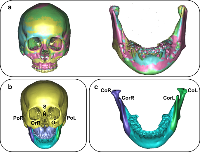
The skull model, was separated into two models, the cranio-maxiollofacial model and mandibular model. Through the use of the surface-best fit registration method20, the 3D cranio-maxiollofacial models and mandibular models of T1, T2, and T3 were superimposed on T0 ones (Fig. 1a) consecutively with the aid of the SimPlant Pro software.
(a) Cranio-maxillofacial and mandibular models of T0-T3 with surface-best-fit method (yellow: T0, pink: T1, blue: T2, green: T3). (b) Bony landmarks of cranio-maxiollofacial were chosen to establish coordinate systems. (c) Bony landmarks of mandibular models were chosen to establish coordinate systems.
Bony landmarks of the cranio-maxiollofacial models (Fig. 1b) and mandibular models (Fig. 1c) were chosen by experienced surgeons to establish the coordinate systems separately (Table 2).
Coordinate system of cranio-maxiollofacial model
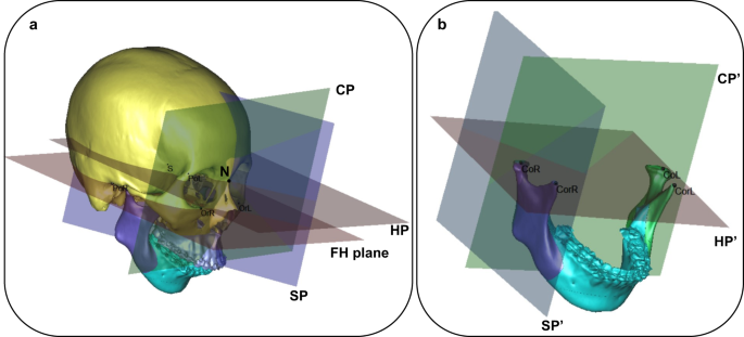
Cranial segment, which remain unchanged before and after surgery, was defined as the reference coordinate system of the 3D cranio-maxiollofacial model (Fig. 2a).

(a) Coordinate systems of cranio-maxiollofacial model with 45°angle. (b) Coordinate systems of mandibular model with 45°angle.
The horizontal reference plane (HP): parallel to the FH plane, which was constructed on both sides of Po and left side Or, passing through N.
The midsagittal plane (SP): perpendicular to the horizontal plane passing through N and S.
The coronal plane (CP): perpendicular to the horizontal and midsagittal plane passing through N.
N point was defined as the original point of the coordinate system.
Coordinate system of mandibular model
For T1, T2 and T3 mandibular models, Co L/R and Cor L/R remain unchanged after surgery, which could be used to defined the reference coordinate system of mandibular model (Fig. 2b).
The mandible-body horizontal reference plane (HP’) was constructed on Co L/R and CorR.
The mandible-body midsagittal plane (SP’) was drawn perpendicular to the horizontal plane passing through CoR and CorR.
The mandible-body coronal plane (CP’) was drawn perpendicular to the horizontal and midsagittal plane passing through CoR.
CoR was defined as the original point of the coordinate system.
In order to precisely measure and analyze the changes, the target cranio-maxiollofacial model was defined as cranial segment and maxillary segment, and the target mandibular model was referred as mandibular-body segment and bilateral ramus segments. We can choose a series of remarkable anatomical landmarks for describing the position of each segments, while three mutually perpendicular planes for describing their posture were also used. Therefore, position and posture of each segment could be defined separately as follows:
Cranial segment: position/posture: Cranial segment, which remain unchanged before and after surgery, was defined as the reference coordinate system of the 3D cranio-maxiollofacial model. So the landmarks of cranio-maxiollofacial model (Fig. 1b) was defined as the position of cranial segment, and the three coordinate planes (Fig. 2a) as its posture.
Maxillary segment: position: In order to describe the position of maxilla, several clinically significant anatomical landmarks were chosen by experienced surgeon. Skeletal landmarks A, SPC, SP6L and SP6R (Table 2) were chosen to describe the position of maxillary segment.
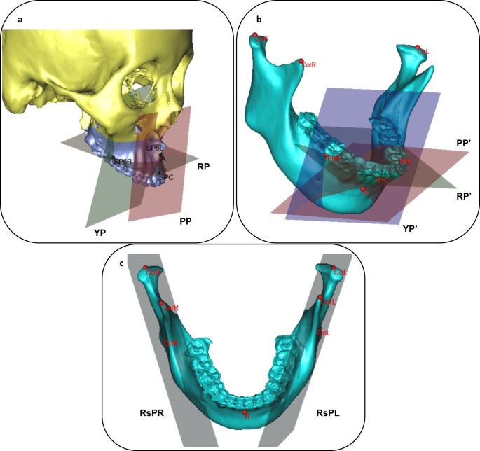
Maxillary segment: posture: Based on the these landmarks, we defined 3 posture planes (Fig. 3a).

(a) Posture plane (PP, RP and YP) of maxillary segments. (b) Posture plane(PP, RP and YP) of mandible-body segment. (a) Bony landmarks and posture planes of bilateral ramus segments.
yaw plane (YP): passing through 2 points (SP6L, SP6R) and normal to HP;
pitch plane (PP): passing through 2 points (A, SPC) and normal to SP
roll plan (RP): passing through 2 points (SP6L, SP6R) and normal to CP
Mandible-body segment: position: In order to describe the position of mandibular-body, several clinically significant anatomical landmarks were chosen by experienced surgeon. Skeletal landmarks B, IPC, IP6L and IP6R (Table 1) were chosen to describe the position of mandibular-body segment.
Mandible-body segment: posture: Based on the these landmarks, we defined 3 posture planes (Fig. 3b).
yaw plane (YP’): passing through 2 points (IP6L, IP6R) and normal to HP’;
pitch plane (PP’): passing through 2 points (B, IPC) and normal to SP’;
roll plan (RP’): passing through 2 points (IP6L, IP6R) and normal to CP’.
Ramus segments: position: Several clinically significant anatomical landmarks were chosen to describe the position of the ramus segments such as CoL/R, CorL/R and GoL/R. (Table 1).
Ramus segment: posture: Because of the shape of ramus segment, we defined its posture as one plane based on these landmarks (Fig. 3c).
Ramus plane (RsP L/R): passing through 3 points (Co, Cor, Go).
The linear differences of anatomical landmarks could represent the positional change of target maxillary segments and mandibular-body segments on each three-dimensional coordinate system (X, Y, Z) (Table 3).
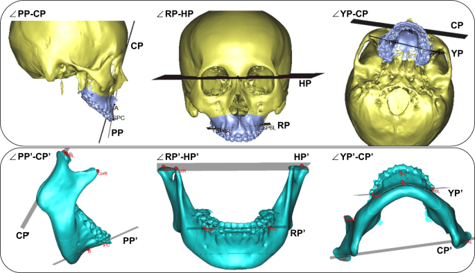
We also measured the angle differences between the posture planes and reference planes of the cranio-maxiollofacial and mandibular model (Table 4, Fig. 4).

Definition of angle between the posture planes (PP, RP and YP) and reference planes on cranio-maxiollofacial model and mandibular model.
Statistical analysis
All measurements were tabulated and sequenced in the different time frame. Differences between groups were considered significant at p ≤ 0.05. One-way ANOVA was used for statistical analysis. All calculations were carried out using the software package SPSS 19.0 (IBM, American).


